

VXC™ Stepper Motor Controller
The new VXC is a plug and play microstepping motor controller / driver with the ability to run up to 4 axes simultaneously. This easy to setup bipolar controller has the ability to be run standalone, or be integrated into a system.
Velmex VXC™ - A Smarter, More Efficient Motor Controller
The Velmex VXC™ Controller is a micro-stepping plug and play motor controller/drive. The high performance VXC can control all Velmex motor-driven positioning products efficiently and effectively.
Simple, easy control for precise positioning of Velmex slides, stages and tables is achieved with an integrated microcontroller that directly controls motor phase switching and all other interface functions. The VXC offers simultaneous coordination of up to 4 axes.
Based off of the proven reliability of Velmex VXM™ Controller, this high performance proven design is a dependable and cost effective solution for high precision positioning requirements. This smart, effective micro-stepping drive is 4 times faster than the VXM Controller and has memory to store up to 13 programs for standalone use. It has many enhanced functions including integrated sensing, braking and troubleshooting detection capabilities.
Like the VXM Controller, it can be used with a PC, Tablet, Laptop or PLC or can run standalone.
See Limits for information on the use of limit switches.

Velmex VXC™ Controller Features
The VXC™ complete stepper motor control solution has the same plug and play features of the VXM Controller while also having numerous improvements, such as microstepping, simultaneous motion control, all in a smaller package.
The VXC Controller/Drive can be configured to control up to four axes with simultaneous coordinated motion or move each axis one-at-a-time.

VXC™ Motor Controller Configurations
VXC-1 – A single-axis programmable control and driver for one motor.

VXC-2 – Controller for two motors (2 axes), each one-at-a-time or simultaneously.

VXC-3 – Controller System for three motors (3 axes), each one-at-a-time or simultaneously.

VXC-4 – Controller System for four motors (4 axes), each one-at-a-time or simultaneously.
VXC™ Specifications


Physical
| Model | Weight | Height (without feet) | Width | Length |
| VXC-1 | 1.3 lbs (0.57 kg) | 1.5” (38.1 mm) | 3.90” (99.1 mm) | 4.12" (104.6mm) |
| VXC-2 | 2.6 lbs. (1.14 kg.) | 3.00” (76.2 mm) | 3.90” (99.1 mm) | 4.12" (104.6mm) |
| VXC-3 | 3.9 lbs. (1.71 kg.) | 4.50” (114.3 mm) | 3.90” (99.1 mm) | 4.12" (104.6mm) |
| VXC-4 | 5.2 lbs. (2.28 kg.) | 6.00” (152.4 mm) | 3.90” (99.1 mm) | 4.12" (104.6mm) |
Environmental
| Ambient Operating Temperature | 35°-95° F (2°-35° C) |
| Relative Humidity: | 10%-90% (non-condensing) |
Function
| Motor Compatibility | NEMA 11 to NEMA 34 | Half-step/Micro-step hybrid stepping motors |
| Number of axis | up to 4 | |
| Steps per revolution | 400 with 1.8° (200 step) motor, | 800 with .9° (400 step) motor |
| Program Storage | 13 programs | |
| Interface | USB-2.0 or RS422 (Configuratable to RS232) | |
| Auxiliary inputs/outputs | 4 in/2 out | |
| Speed Range (pulses/sec) | 1 to 6000 | |
| Default Baud Rate | 57,600 | |
| Maximum Baud Rate | 57,600 | |
| Program language | ASCII Characters | Labview, Matlab, Python |
| Programmable or Stand alone operation | Yes |
Motor Drive
| Type: | Bipolar, 31.25 kHz PWM |
| Output | 3A RMS, 8A peak |
Cabling
| Integrated 10 ft (3 meter) long Motor Cable, 10 ft (3 meter) Detachable Limit Cable |
I/O
| All inputs & outputs impedance protected and with internal diodes to +5V and Gnd |
| Outputs: | 5V TTL 25mA maximum |
| Inputs: | 5V TTL compatible active low (4.7k ohm internal pull-up) |
| Limits and Home input optoisolated (powered by onboard user 10V) |
Serial Ports
| USB: USB 2.0 standard, micro B connector, electrostatic discharge (ESD) protection > 4 kV |
| Host controlled/programed with USB-2.0 and RS-422 Interfaces, 8 Data, No Parity, 1 Stop, 57600 (default), 9600, 19200, 38400 baud rate settable. |
| RS-422 (Configurable to RS-232): Four wire full duplex transceiver with ±18-kV IEC ESD protection |
| Signals: Tx-, Tx+, Rx-, Rx+ |
| Biasing Resistors on Rx: 4.7k Ohms |
| Termination: None |
Electrical Requirements
| AC Power Supply | 100-240VAC 1.5A 47-63Hz | IEC/EN/UL 62368-1, EN55032 and CISPR/FCC Class B, CoC Tier 2 and DOE Level VIcompliant |
| VXC Controller Power | 24VDC 3A |
Options and Accessories
The VXC controller is specifically designed and rigorously tested to work seamlessly with the motors we offer. We have carefully selected high-quality, reliable motors and optimized our control system to ensure optimal performance. For the best results, we strongly recommend using our Genuine Leadshine motors with the VXC controller. In our experience, the investment in these motors is well worth it to guarantee a smooth and efficient system.


Analog Joystick
Direct the VXC Controller with use of a joystick.
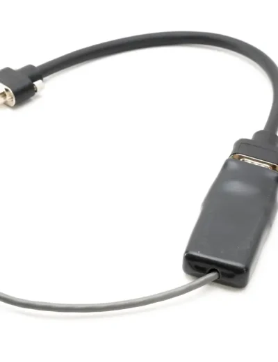
Auxiliary I/O Breakout Module
The Breakout Module is a convenient method to interface to the VXC's auxiliary I/O.

Digital Joystick
Direct the Stepper Motor Controller with use of a joystick.
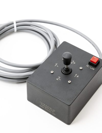
Heavy duty 2-axis Joystick
Direct the VXC Controller with use of a joystick.
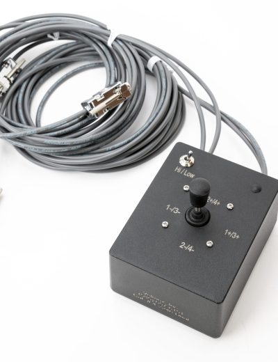
Heavy duty 2-axis Joystick
Direct the VXC Controller with use of a joystick.
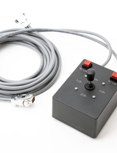
Heavy duty 4-axis Joystick
Direct the VXC Controller with use of a joystick.
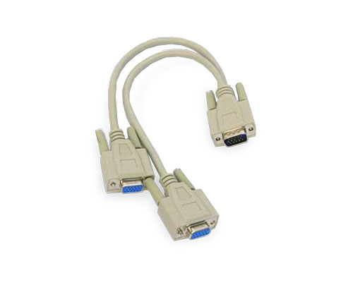
I/O Splitter
The I/O Splitter allows both a joystick and the Auxiliary I/O Breakout Module to be connected to the VXC at the same time.

Legacy Motor and Limit Cable Adapters
Motor and limit cables and various adapters are available to connect select obsolete Velmex products to current Velmex products.

Limit/Home Breakout Module
The optional Limit/Home Breakout Module provides a reliable method for mating to the VXC limit cable when using non Velmex actuators
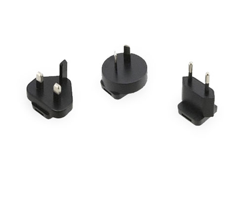
Power Adapter Plug – Australia
A variety of international-rated power adapters are available.
Power Adapter Plug – European
A variety of international-rated power adapters are available.
Power Adapter Plug – United Kingdom
A variety of international-rated power adapters are available.
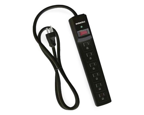
Power Strip
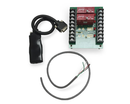
Relay Modules
Relay modules with 2 or 4 outputs function as a dry contact switch.
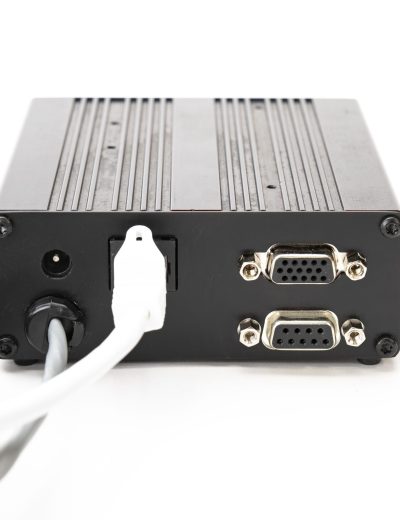
RS-232 Rear Port Option
Optional RS-232 port (9 pin D-sub) connection on rear of control
RS-422 to RS-232 DB9 D-sub Female Adapter Converter
These adapters provide convenient connection/conversion with the front panel RS-422 port.

Speed Pot
To control speed at the VXC.

Thumb wheel
Thumb wheel program selector switch allows you to easily select and switch between programs loaded in the VXC.

USB Serial Cable
This USB 2.0 A Male to USB 2.0 Micro B Male connects your computer to the VXC USB port.

VXC Power Supply
The universal power supply is standard with all VXC Controllers. It can also be ordered separately.
Special Options Include Input terminal for data entry, OEM mountable joysticks, Potentiometer speed input, Network and wireless adapters, Open chassis for OEM embedded applications, Thumbwheel program selector switch, Custom programming, Customized cables & connectors.
For details on Limits which attach to the stages, visit the Limits page.
VXC App
The VXC App is a software package with a simple-to-use interface that coordinates communication between the computer, the VXC Controller axis model and ultimately the stepper motor(s). It makes it easy to set-up and program the VXC to control Velmex motorized positioning systems.
See DOWNLOADS for more information on the VXC App.
Applications and Examples
The example displayed may be a custom configuration, designed to the customer’s specifications; and not offered as a standard product. Custom configurations could contain custom, externally-fabricated components.
Pictured in our gallery are examples of configurations and systems that may also include other Velmex products. Product and accessory offering is subject to change and availability.


This B48 Series Motorized Rotary Stage is being controlled by a Velmex VXC-2 Stepper Motor Controller.

Here is an example of a BiSlide® Motorized Linear Stage being positioned using the VXC-2 Step Motor Controller
Downloads
The majority of CAD drawings found in our Technical Library are Step (.stp) files. You will also see .dxf, .dwg, .sat and .pdf files. For .STP files, you may need to right click on the download button and save the “target” or “link”. If you require a different format or cannot located the drawing you require, please contact us.
| Title | Summary | File Type | Link | hf:file_type |
|---|---|---|---|---|
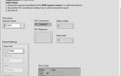
| LabVIEW Examples – Ver. 2.40 | Examples of VXC Commands for LabVIEW | zip | zip | |
| LabVIEW Examples – Ver. 2.50 | Examples of VXC Commands for LabVIEW | zip | zip | |
| Serial Port Diagnostics | Diagnostics for Driver Issues (Version 3.1.0) | exe | exe | |
| Velmex Stepper Motors | Specs and wiring for all CURRENT Velmex Stepper Motors for use with VXC Control | |||
| VXC 24V Power Supply TRH70A240.stp | STEP file of VXC 24V power supply | stp | stp | |
| VXC 28V Power Supply TRH100A280.stp | STEP file of VXC 28V power supply | stp | stp | |
| VXC App | Velmex App for configuration & testing of VXC controller Build 05.28.25 | zip | zip | |
| VXC Spec Overview | Overview of the VXC Stepping Motor Controller | |||
| VXC Users Manual | Operating Manual: Specifications, features, function, programming details for the VXC Controller (Version 5.21 Rev 09-01-26) | |||
| VXC-1 – Quick Start.pdf | Instructions: Set-up, connecting and configuring the VXC-1 with a Velmex stage | |||
| VXC-1 Outline Assembly With 2 Cleats.stp | STEP file of VXC-1 assembly with 2 mounting cleats | stp | stp | |
| VXC-1 Outline Assembly With 4 Cleats.stp | STEP file of VXC-1 assembly with 4 mounting cleats | stp | stp | |
| VXC-2 – Quick Start.pdf | Instructions: Set-up, connecting and configuring the VXC-2 with a Velmex stage | |||
| VXC-2 Outline Assembly With 2 Cleats.stp | STEP file of VXC-2 assembly with 2 mounting cleats | stp | stp | |
| VXC-2 Outline Assembly With 4 Cleats.stp | STEP file of VXC-2 assembly with 4 mounting cleats | stp | stp | |
| VXC-2 Outline Assembly With Side Mounting.stp | STEP file of VXC-2 assembly with side mounting plates | stp | stp | |
| VXC-3 – Quick Start.pdf | Instructions: Set-up, connecting and configuring the VXC-3 with a Velmex stage | |||
| VXC-3 Outline Assembly With 2 Cleats.stp | STEP file of VXC-3 assembly with 2 mounting cleats | stp | stp | |
| VXC-3 Outline Assembly With 4 Cleats.stp | STEP file of VXC-3 assembly with 4 mounting cleats | stp | stp | |
| VXC-3 Outline Assembly With Side Mounting.stp | STEP file of VXC-3 assembly with side mounting plates | stp | stp | |
| VXC-4 – Quick Start.pdf | Instructions: Set-up, connecting and configuring the VXC-4 with a Velmex stage | |||
| VXC-4 Outline Assembly With 2 Cleats.stp | STEP file of VXC-4 assembly with 2 mounting cleats | stp | stp | |
| VXC-4 Outline Assembly With Side Mounting.stp | STEP file of VXC-4 assembly with side mounting plates | stp | stp |
Knowledge Base
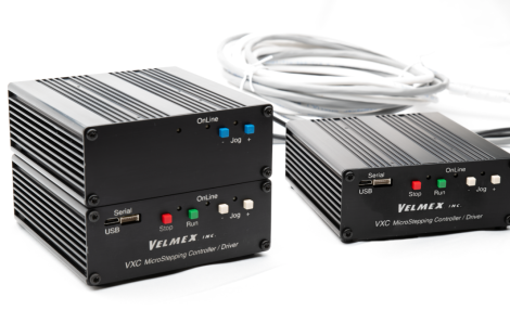

VXC Controllers have serial numbers which can be located on the back of the device.

Yes, VXC configurations can control up to 4 motors simultaneously or 1 motor at a time. Additional VXC Controllers can be added to control additional axes, however, the most that can be operated simultaneously is 4.
In order to program the VXC Controller for your specific application, it should be connected to a PC, Laptop, Tablet or PLC. Once downloaded with a program, it can operate without the computer connection.
For both the Velmex VXM and the VXC Controllers, a driver is integrated with the motor controls. If a separate controller was purchased, it would require a driver in order to move and position the Velmex stage.
Yes, if you have your own motors and controllers, you can use them with Velmex motor-ready products. Like the VXM Controller, the VXC Controller, however, has been specifically designed to optimize stepper motor control. Its a very dependable and low cost solution for high precision positioning requirements. Velmex motorized stages, motors and the VXC Motor Controller come as a complete system, ready to plug in. Click on the “Specifications Tab” above for more details and specifications.
Check the configuration settings. The VXC needs to be set-up to recognize the specific motor and axis it is controlling. If after configuration, the VXC does not appear to be controlling the motors properly, follow the troubleshooting steps in the VXC Users Manual and run the System Diagnostics.
The VXC Controller has a fault indicator LED.
| Controller Configuration | 1 Axis, 2 Axes, 3 Axes, 4 Axes |
|---|

