Guide to Motion / Positioning Systems
Linear Stage / X Axis Stage
One axis stage (also called a slide or translation stage) travels in a straight line along one plane or axis. The stage can be horizontal. It can be vertical which would be on a Z axis. It is also possible with some stages to invert them horizontally so that the payload is “below” the stage. A payload is mounted or placed on the carriage of the stage.

The stage usually consists of:
• A base (ways) on which the carriage rides. The base on a Velmex stage is a dovetail extrusion.
• A carriage which carries the payload.
• A means to control the position of the carriage. This can be a crank and knob, a graduated knob, a micrometer head or a motor. On a Velmex Free Slide, position is controlled by the operator pushing the carriage into position. Stages can also be operatoperated with motors. Most of Velmex’s offering can accommodate stepper motors, but also Servo Motors and DC Motors.
• Additional options can be added with include: locks, counters, limit switches, encoders, etc.
XY Stage

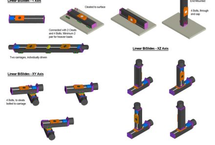
An XY stage is 2 linear slides mounted together. One stage/slide is on the X axis and the other is on the Y axis. Usually these are horizontal but can be in an inverted horizontal configuration. The top (or Y) slide’s base is mounted to the bottom (or X) slide’s carriage. The payload is then placed on the Y’s carriage.
Load maximum for the bottom or X slide must now be calculated including the weight of the Y slide and any components used to attach it to the X slide. The stage can be manually- or motor-driven.
XY Table

An XY stage is often considered an XY table. However, there are specific configurations XY Table that usually are comprised of a larger base and carriage platform, hence the name, XY Table. An XY Table still travels horizontally in X and Y. The larger carriage plate supports a payload with a larger physical geometry. Both the base plate and the platform plate are affixed to their corresponding slide in the center of the plate. The the maximum load capacity is now calculated including the weight of the Y slide and the carriage platform. XY stages and tables have a limited range of motion.
An XY Table can also be comprised of 2 linear slides traveling in tandem on the X axis and 2 traveling in tandem on the Y axis. In this configuration the tandem slides affixed at the outside perimeter of the base plate and platform plate. Frequently this type of XY table will have an aperture in the center because the slides are attached at the perimeters of the base and platform plate.
Elevating Table

There are a number of different configurations of elevating tables in the motion industry. One is usually called a lift table and frequently uses a scissors mechanism to move the top platform up and down.
Another form of elevating table uses a linear slide mounted on the Z axis to a base plate. The payload can be mounted directly to the carriage or it can be mounted on a L-shaped platform bracket which is in turn mounted to the carriage.
Small Elevating tables can be driven manually or motorized. Larger tables can also be pneumatic or hydraulic.
XZ Stage

An XZ stage is similar to an XY stage with 2 linear slides mounted together. However, in this configuration the base slide is on the X axis and the other is on the Z axis. The end plate of the Z slide is mounted to the carriage on the X slide at a right angle. The payload is then placed on the Y’s carriage or on a L-shaped platform bracket which is in turn mounted to the carriage.
Load maximum for the bottom or X slide must now be calculated including the weight of the Z slide and any components used to attach it to the X slide. This is more than likely also going to be a cantilevered load. The stage can be manually- or motor-driven.
XYZ System

In an XYZ system there are 3 axes. One linear slide moving on the X axis; one slide moving on the Y axis and one slide moving on the Z axis. The linear slide in Z is mounted at a right angle on to the carriage on the Y axis.
Load maximum for the base or X slide must now be calculated including the weight of the X slide and the weight of the Z slide and any components used to attach them to the other slides. The system can be manually- or motor-driven.
Gantry System

Gantries are composed of linear slides. Their linear movements are in three axes, X, Y, and Z. The slide with the payload is suspended above the work space either on other linear slides or a framework. Frequently the X axis has 2 linear slides moving in tandem.
Because the payload is suspended the Gantry system has the best accessibility to the surrounding work space. Frequently a Gantry system is motorized.
Rotary Table

Rotary tables are positioning devices that rotate the payload 360° around a center axis. When operating or mounted horizontally, the table is rotating around a vertical axis. When mounted vertically or on its side/end, the table is rotating around a horizontal axis. The revolving axis is a theta axis.
Rotary tables can be manually- or motor-driven. Large scale rotary tables are frequently found in CNC machining operations. They are also used in indexing or pan and tilt operations.
Combination System

A combination system is a multi-axis system that combines linear and rotary stages. They can be relatively simple with two or three axis or extremely complex with multiple axes in X, Y, Z and theta and any combination thereof, creating compound movements.
A motorized, multi-axis system could also have synchronized movements through the use of a motor controller.
Abbe Error
Acceleration
Accuracy
Actuator
Advance
Axes of Motion

X: Linear motion in positioning direction (Horizontal)
Y: Linear motion perpendicular to positioning direction
Z: Vertical linear motion Theta -- Θ -- Frequently referring to movement on a rotating plane or circular direction. Rotational direction also is referred to as:
A or Roll: Rotary motion around the X axis
B or Pitch: Rotary motion around the Y axis
C or Yaw: Rotary motion around the Z axis
Axis
Axis of rotation
Back Driving
Backlash
Ball Screw
BiPolar Stepper Motor
Bus Cable

C.O.S.M.O.S.™

Cantilevered load

Closed Loop
Coefficient of friction
Controller

A multi-axis system where the movement and position of each axis is dependent on the other. The movements are often controlled by a motor controller. The motion in the Velmex system in the Geo Man video is an example of coordinated motion.
Critical Speed
Damping, Damper
Detent Torque
Deviations from Straightness
• Run Out, which is the deviation from a straight line in the horizontal plane.
• Bow, which is the vertical plane deviation from a straight line in the upward direction.
• Twist, which resembles a corkscrew effect, is twisting in the direction of the slide.
(See Flatness of Travel and Straight Line Accuracy)
Dovetail

Drive Nut

Duty Cycle
Dwell Time
Dynamic Load
Eccentricity

Encoder

— Encoder – Absolute
— Encoder – Incremental
— Encoder – Inductive Scale
— Encoder – Magnetic Scale
— Encoder – Rotary
— Encoder – Optical
Flatness of Travel

Environment
One of the factors that can effect the efficiency of the stage. Can refer to temperature, contaminants present, cleanroom or vacuum environment, etc. For Velmex Stages see Vacuum Applications.
Free Slide
Full step
Gantry
Gearbox
Half step
Home Switch
Incremental Move (Relative move)
Indexing
Lead Screw

Left-Right Hand Screw
Limit switch

Limits
Linear Motion
Load
Load Capacity
Micrometer

Microstep
Misstep
Momentary Load
Noise
Normal Centered

Orientation

Pitch (on Lead Screw)

Pitch (Direction)
Potentiometer
Repeatability

Resistance
Resolution
Resonance
Roll
Run Out (Horizontal Run Out)
Screw Lead Accuracy
Servomotor
Settling Time
Slide
Slider

Speed
StabilNut™

Stage
Static Load
Stepper Motor
Step and Direction
Stiffness
Straight Line Accuracy

Thrust
Thrust Bearing

Torque
Translation
Travel Distance
Traverse
Unipolar Stepper Motor
Velocity
Ways

Whipping
Wobble

Yaw
Typical Modes or Functions for Motion Stages
Generally there are two functional uses of motorized positioning devices: Scanning or Positioning.
Scanning
In this category, the objective or work to be accomplished occurs while the slider carriage is in motion. Scanning functions can be further subdivided into two types: scanning at a single, fixed speed or at one of a range of user selectable variable speeds.
Scanning or feeding at a single, fixed speed – A probe, sensor, cutter, dispenser, transducer or some other object is moved at a single, constant speed. An AC synchronous motor, DC gear motor or stepping motor achieves this function within 0.1% or less speed variation. Linear speed is a function of the motor and lead screw pitch selected.
Scanning or feeding at a selected speed – The objective is same as the above. However, an added advantage is the ability to select one scanning speed from a range of motor speeds via a motor control. There are three possible configurations of speed control: unregulated, regulated and programmable.
Unregulated Speed Control – Typically, a high slip AC induction motor speed will fluctuate due to varying loads and voltages.
Regulated control – In this system, the control senses the motor speed and makes the necessary adjustments. Using a permanent magnet DC motor and speed control, speed regulation is achieved by sensing back-EMF; accuracy is the 1-2% range.
In some instances, an optional circuit can be added to return to the “home” position at maximum motor speed.
Programmed control – A DC stepper motor can be programmed to run at a predetermined speed. Scan rates can be varied as a function of position. Complex patterns such as raster scan and auto reverse are also easily programmed.

Positioning
The objective is to move to a target position and either stop or move again. This is commonly achieved by using a stepper motor and an accurate lead screw. The motor is incremented/programmed a predetermined number of steps to achieve the desired position. The position can be relative or absolute.