


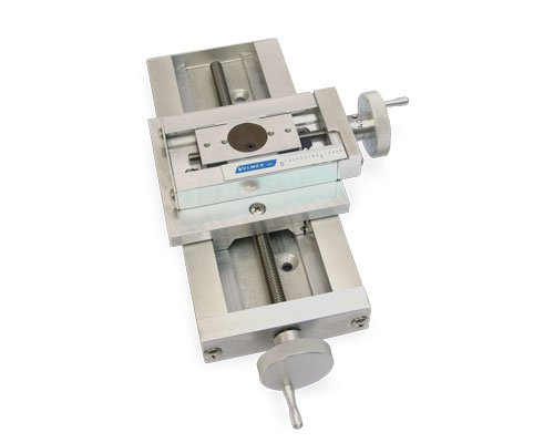
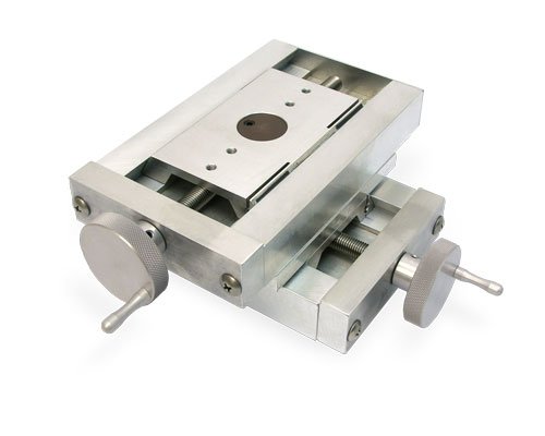


UniSlide® A40 Series – Screw Drive
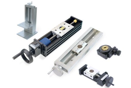
The A40 Series UniSlide® Screw Drive Models provide precise, repeatable linear motion controlled by a lead screw, making them ideal for applications requiring accurate, manual positioning. A range of lead screw diameters is available—from 3/8″ to 1/2″ and 10 mm—each offering different advance rates to match the resolution and speed requirements of your application.

Features
Manual lead screw operation for precise linear positioning
Multiple lead screw diameters and advance rates available
Precision dovetail bearing for smooth, low-friction motion
Travel distances from 2″ to 38″
Supports up to 100 lbs horizontal load
Low-profile, rigid aluminum construction
Compact, durable design suitable for a wide range of manual positioning tasks
Specifications
Factors such as size of the motor, size of the payload, travel distance, mounting direction/plane, etc. effect the actual capability of any assembly. Please contact Velmex Application Engineers to configure a system that will meet your exact requirements.
| Operating temperature | 0 to 180° F (-18 to 82° C) |
Properties of Velmex Stages - Information on stage composition, tolerances, wear and design for specialty applications.
Load Parameters - Definitions and parameters that effect the various load ratings.
UniSlide® A40 Dimensions

| Standard | Metric | |
| Travel Distance | 2" - 38" | 5.08 – 96.52 cm |
| Base Length | 6" - 42" | 15.24 – 106.68 cm |
| Slider Length | 4" | 10.16 cm |
| Weight | 2.4 – 11 lbs. | 1.1 – 5 kg. |
| Height** | 1.06" | 2.69 cm |
| Width | 4" | 10.16 cm |
‡ Standard travel distances available are in 3″ increments.
UniSlide® A40 Load Calculations
| Load Capacity | lbs. | kg. |
| Maximum Horizontal Load | 100 lbs. | 45.5 kg. |
| Horizontal Central Load | 100 lbs. | 45.5 kg. |
| Cantilevered Load | 130 lb-in | 14.7 N-m |
| Vertical Central | 50 lbs. | 22.7 kg. |
| Load Normal (LN)* | 40 lbs. | 18.14 kg. |
| Load Thrust (LT)† | 20 lbs. | 9.07 kg. |
| Cantilever Side (LCS)* | 32 lb-in | 3.62 N-m |
| Cantilever Inline (LCI)* | 64 lb-in | 7.23 N-m |
* Normal Operating Loads are less than the maximum.
† 5 lbs. max for Rapid Advance models.
Lead Screw Specifications
| Repeatability | 0.00015″ (4 microns) typical |
| Straight line accuracy | 0.003″ (0.076 mm) over entire travel distance. Higher accuracy 0.0015″ (0.038mm) available |
| Screw lead accuracy | 0.003″/10″ (0.076 mm/25 cm) 0.0015″/10″ available. Consult factory. |
English Thread Lead Screws
| Pitch | Backlash Typical | UniSlide™ Code | |||||||
| Turns per inch | Advance per revolution | English | Metric | Degrees | Standard Accuracy | With Scale and Vernier - Standard Accuracy | With Graduated Knob - Precision Accuracy | Division on Graduated Knob | Lead Screw Diameter |
| 40 | 0.025" | 0.00013" | 0.003 mm | 1/200 rev or 1.8° | C | CE | P40 | 25 | 3/8" |
| 20 | 0.05" | 0.00025" | 0.006 mm | 1/200 rev or 1.8° | B | BE | P20 | 50 | 3/8" |
| 10 | 0.1" | 0.0005" | 0.013 mm | 1/200 rev or 1.8° | W1 | W1E | P10 | 100 | 3/8" |
| 5 | 0.2" | 0.001" | 0.025 mm | 1/200 rev or 1.8° | W2 | W2E | P5 | 200 | 3/8" |
| 2.5 | 0.4" | 0.002" | 0.051 mm | 1/200 rev or 1.8° | W4 | - | - | - | 3/8" |
Metric Thread Lead Screws
| Pitch | Backlash Typical | UniSlide® Code | |||||||
| Turns per cm | Advance per revolution | English | Metric | Degrees | Standard Accuracy | With Scale and Vernier - Standard Accuracy | With Graduated Knob - Precision Accuracy | Division on Graduated Knob | Lead Screw Diameter |
| 10 | 1 mm | 0.0002" | 0.005 mm | 1/200 rev or 1.8° | K1 | K1M | Q1 | 100 | 10 mm |
| 5 | 2 mm | 0.00039" | 0.01 mm | 1/200 rev or 1.8° | K2 | K2M | Q2 | 200 | 10 mm |
*Adjustable nut models (A25,A40,A60) can have backlash adjusted to near 0. Manual applications only
Options/Accessories for A40 UniSlide® Assemblies

A4000XY Adapter Plate
To mount an A40 or MA40 Series UniSlide to another A40 or MA40 Series or to an A25 or MA25 Series in XY. (The A40 or MA40 would be the base stage.)

A4000XZ Adapter Plate
Mount an A40 or MA40 Series UniSlide or an A25 or MA25 Series vertically to another A40 or MA40 Series in XZ.

A4001XZ Adapter Bracket
Mount an A40 or MA40 Series UniSlide (6″- 9″) or an A25 or MA25 Series (6″- 9″) vertically to another A40 or MA40 Series in XZ. Can also mount two B4800TS Rotary Tables at right angles.

A6000TX Adapter Plate

A6000XY Adapter Plate
Mount an A60 or MA60 Series UniSlide to another A60 or MA60 Series or to an A40 or MA40 Series in XY.

A6000XZ Adapter Plate
To mount an A60 or MA60 Series UniSlide to another A60 or MA60 Series or to an A40 or MA40 Series in XZ. (The A60 or MA60 would be the base horizontal stage.)

A6001XZ Adapter Bracket
Mount an A60 or MA60 Series UniSlide to another A60 or MA60 Series (up to 12″) or to an A40 or MA40 Series (up to 12″) in XZ.

B4003XZ Adapter Bracket
Mount a vertical A25, MA25, A40, or MA40 Series UniSlide® Assembly (12″–15″ travel) to a horizontal A40 or MA40 Series UniSlide® base stage in an XZ configuration.
B4004XZ Adapter Bracket
To mount an A40 or MA40 Series UniSlide to another A40 or MA40 Series (over 15″) or to an A25 or MA25 Series (over 15″) in XZ. (The A40 or MA40 would be the base horizontal stage.)

B5990TXZ-BK Adapter Plate
Use this bracket to mount two B5990TS Rotary Tables at right angles to each other or to mount a B5990TS to a UniSlide® Linear Stage.

B6003XZ Adapter Bracket
To mount an A60 or MA60 Series UniSlide to another A60 or MA60 Series (12″- 15″) or to an A40 or MA40 Series (12″- 15″) in XZ. (The A60 or MA60 would be the base horizontal stage.)
B6004XZ Adapter Bracket
To mount an A60 or MA60 Series UniSlide to another A60 or MA60 Series (over 15″) or to an A40 or MA40 Series (over 15″) in XZ. (The A60 or MA60 would be the base horizontal stage.)

UniSlide® Slider Lock
This lock is mounted at the mid-point on the base and is tightened to prevent slider movement.

UniSlide® Thumbscrew-on-Lead-Screw Lock
An easy method to affix the slider utilizing a simple thumbscrew on the lead screw at the end bearing block of each axis.

UniSlide® Traveling Slider Lock (-TSL)
This lock attaches to the slider to lock the carriage in place.

A25 / A40 Series Right Angle Gearbox
Ideal for tight spaces or applications where access to the end of the stage is limited.

A40 Alternative Knobs
A variety of knob styles can be substituted for the standard knob on any UniSlide® Assembly.
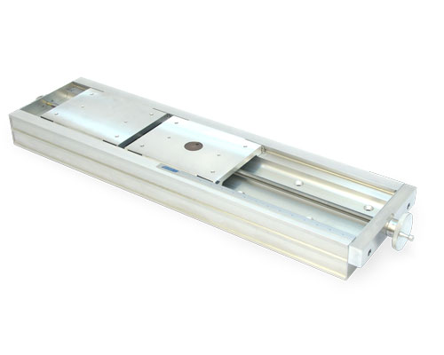

B49 Platform Shelf
Platform shelf from UniSlide® A40 and MA40 Elevating Tables that can be used on vertical UniSlide® Assemblies.

Left-Right Screw Motion
This configuration enables two carriages to travel along a shared axis using a single lead screw while moving towards or away from each other.

Optional Finishes
Many Velmex Products come standard with a brushed aluminum finish. Optional finishes including Black Anodizing are available.

Slider Lengths
All UniSlide® Assemblies are available with a variety of carriage (slider) lengths to suit different application needs.
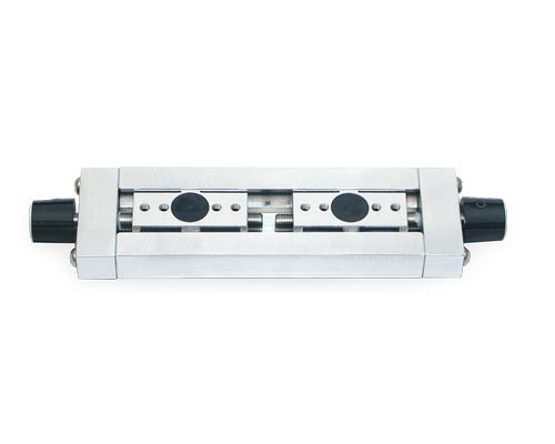
Two Independent Carriages
Separate and precise positioning along the same linear axis using two lead screws.

UniSlide® Way Covers
Way Covers protect the slider and dovetail base from dust, dirt and grit that could hamper the efficient operation of the slide, thereby extending the life of the slide.

UniSlide® Revolution Counter
The mechanical counter provides a convenient lead screw revolution count. This aids in determining position and providing a reference number for the location of the carriage / slider.

Velmex offers a multitude of options and accessories for all its products. Usually an option or an accessory will address your requirements. When it doesn’t, we can make custom modifications, including:
• Additional holes or slots. (A drawing is required.)
• Intermediate plates to mount your payload
• Special or in between lengths of the dovetail base
• Lead screw shaft extensions
• Choice of drive nut materials, including brass and Vespel
We can also offer customized configurations to address special environmental and vacuum applications.
Applications and Examples
Note: the example displayed may be a custom configuration, designed to the customer’s specifications; and not offered as a standard product. Custom configurations could contain custom, externally-fabricated components.

Downloads
The majority of CAD drawings found in our Technical Library are Step (.stp) files. You will also see .dxf, .dwg, .sat and .pdf files. For .STP files, you may need to right click on the download button and save the “target” or “link”. If you require a different format or cannot located the drawing you require, please contact us.
| Title | Summary | File Type | Link | hf:file_type |
|---|---|---|---|---|
| A4006xx-S4.stp | Lead screw, basic knob and crank, 2″ Travel | stp | stp | |
| A4009xx-S4-TL.stp | Lead screw, basic knob and crank, 5″ Travel, thumb lock | stp | stp | |
| A4009xx-S4.stp | Lead screw, basic knob and crank, 5″ Travel | stp | stp | |
| A4012xx-S4.stp | Lead screw, basic knob and crank, 8″ Travel | stp | stp | |
| A4015xx-S4.stp | Lead screw, basic knob and crank, 11″ Travel | stp | stp | |
| A4018xx-S4.stp | Lead screw, basic knob and crank, 14″ Travel | stp | stp | |
| A4021xx-S4.stp | Lead screw, basic knob and crank, 17″ Travel | stp | stp | |
| A4024xx-S4.stp | Lead screw, basic knob and crank, 20″ Travel | stp | stp | |
| A4027xx-S4.stp | Lead screw, basic knob and crank, 23″ Travel | stp | stp | |
| A4030xx-S4.stp | Lead screw, basic knob and crank, 26″ Travel | stp | stp | |
| A4033xx-S4.stp | Lead screw, basic knob and crank, 29″ Travel | stp | stp | |
| A4036xx-S4.stp | Lead screw, basic knob and crank, 32″ Travel | stp | stp | |
| A4039xx-S4.stp | Lead screw, basic knob and crank, 35″ Travel | stp | stp | |
| Manual UniSlide® Dimensional Drawings | Dimensional drawings for the 5 Series of Manually Operated UniSlide® Linear Stages | |||
| UniSlide Manual Spec Overview | Overview of Manual UniSlide® Assemblies | |||
| UniSlide® Users Manual | Operating and Service Manual for UniSlide® Stages |
Knowledge Base




| Motion | Linear |
|---|---|
| Maximum Travel | 80" (203.2 cm) |
| Minimum Travel | 5" (12.7 cm) |

