

Motorized BiSlide® Tandem Linear Stage
Increase load and cantilever capabilities of BiSlide® with this combination of lead screw and free motion stages mechanically connected with carriages operating in tandem.
A combination of a Motorized Lead Screw Driven BiSlide® Assembly and a Free Motion assembly mechanically connected so that the carriages operate in tandem. The increased stiffness of Tandem BiSlide® Assemblies can carry larger loads and increases the cantilever capabilities. Additional Free Motion assemblies may be connected to further increase capabilities if required.
Constructed with hard-coat anodized, aluminum dovetail ways and smooth motion PTFE bearings; BiSlide® assemblies deliver higher rigidity for longer life and more precise movement.
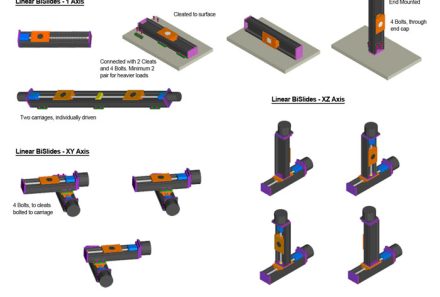
Because BiSlide® components are interchangeable, they can easily be reconfigured as the need arises. One, two and three axis systems are created by simply bolting together standard components utilizing the advantages of T-slot framing.

Features
Maximum Horizontal Load Capacity – 600 lbs. (272.15 kg.)
Maximum Vertical Load Capacity – 100 lbs. (45.4 kg.)
Maximum Travel Distance – 80″ (203.2 cm)
Uses the proven StabilNut II™ drive nut design
Specifications
Factors such as size of the motor, size of the payload, travel distance, mounting direction/plane, etc. effect the actual capability of any assembly. Please contact Velmex Application Engineers to configure a system that will meet your exact requirements.
| Coefficient of friction | .09 typical |
| Coefficient range | 0.04 (Heavy Load Dynamic) to 0.15-0.3 (Lubricated heavy Load Static>1 hour) |
| Operating temperature | 0 to 180° F (-18 to 82° C) |
Properties of Velmex Stages - Information on stage composition, tolerances, wear and design for specialty applications.
Load Parameters - Definitions and parameters that effect the various load ratings.


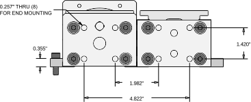
| Standard | Metric | |
| Travel Distance | 5" - 80" | 12.7 – 203.2 cm |
| Base Length | 12.95" – 90.35" | 32.9 – 229.5 cm |
| Slider Length | 5" | 12.7 cm |
| Weight | 12.0– 60.0 lbs. | 5.4– 27 kg. |
| Height | 3.03" | 7.7 cm |
| Width | 6.8" | 17.3 cm |
‡Standard travel distances available are in 5″ increments up to 20″ in length and 10″ increments over 20”.
* Motors sold separately. NEMA 23 units sold with .250″ motor mounting coupling. NEMA 34 units sold with .375″ motor mounting coupling.
BiSlide® Tandem Load Calculations


Note:
Because of the interlocking nature of the BiSlide® carriage and the dovetail ways, the maximum recommended load centered (normal) or under thrust would be comparable whether the slide was upright (Normal – LN), Inverted (LI) or set on the Edge (LE).
To calculate equivalent center load for a cantilevered load: Lc = (Dx L/2) + L
| Dynamic Load | Static Load | Momentary Load | ||||
| Load Capacity | lbs. | kg. | lbs. | kg. | lbs. | kg. |
| Maximum Centered | 600 lbs. | 272.2 kg | 600 lbs. | 272.2 kg | 1000 lbs. | 453.59 kg |
| Thrust | 100 lbs. | 45.4 kg. | 200 lbs. | 90.7 kg. | 300 lbs. | 136.1 kg. |
| Cantilevered | 500 lbs.-in. | 56.5 n-m |

Deflection: a = 0.000011 degrees / in-lb (F x d = in-lbs)
Lead Screw Specifications
English Thread Lead Screws
| Pitch | Backlash Typical | Resolution | BiSlide® Code | |||
| Turns per inch | Advance per revolution | English | Metric | Degrees | English | |
| 2.5* | 0.400" | 0.002" | 0.051 mm | 1/200 rev or 1.8° | 0.001" | E04 |
| 5* | 0.200" | 0.001" | 0.025 mm | 1/200 rev or 1.8° | 0.0005" | E02 |
| 10 | 0.100" | 0.0005" | 0.013 mm | 1/200 rev or 1.8° | 0.00025 | E01 |
Metric Thread Lead Screws
| Pitch | Backlash Typical | Resolution | BiSlide® Code | |||
| Turns per cm | Advance per revolution | English | Metric | Degrees | Metric | |
| 5 | 2 mm | 0.00039" | 0.01 mm | 1/200 rev or 1.8° | 0.005 mm | M02 |
| 10 | 1 mm | 0.0002" | 0.005 mm | 1/200 rev or 1.8° | 0.0025 mm | M01 |
*Not recommended for vertical assemblies because the lead screw could back drive.
More accurate screws are available. Contact a Velmex Application Engineer for more information.
In manually operated applications backlash can be adjusted to near 0.
Resolution specified with standard Velmex motor configurations with 1.8° step angles using VXC Stepping Motor Controller.
| Repeatability | 0.00015″ (4 microns) typical |
| Straight line accuracy | 0.003″ (0.076 mm) over entire travel distance. Higher accuracy 0.0015″ (0.038mm) available |
| Screw lead accuracy | 0.003″/10″ (0.076 mm/25 cm) 0.0015″/10″ available. Consult factory. |
Options/Accessories for Motorized Tandem BiSlide® Assemblies
Several options can be added to BiSlide® Assemblies to make them more versatile and configurable with other Velmex products.

BiSlide® Limits
Limit switches mounted in the track on the side rib of the assembly to prevent over-travel.

NEMA 23 VML231-3.0-D Motor
NEMA 23 Motor for UniSlide®, XSlide®, BiSlide® and B48 Series Rotary Stages

NEMA 23 VML232-4.0-D Motor
NEMA 23 Motor for UniSlide® BiSlide® and B48 Series Rotary Stages
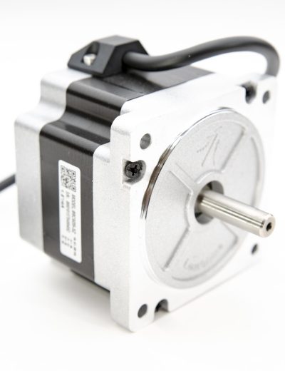
NEMA 34 VML341-4.0-D Motor
Compatible with UniSlide®, BiSlide®, BiSlide® Parallel Coupled, and BiSlide® Belt Driven Assemblies

VRO™ Encoder Readout
The Velmex VRO™ Encoder Readout is a compact one or two axes digital readout for linear and rotary incremental encoders.

VXC™ Stepper Motor Controller
The new VXC is a plug and play microstepping motor controller / driver with the ability to run up to 4 axes simultaneously. This easy to setup bipolar controller has the ability to be run standalone, or be integrated into a system.

IM001-130-131 Plate
Payload plate to expand the carriage (8″ x 8″ x 0.375″)

IM001-130-132 Plate
Payload plate to expand the carriage (12″ x 12″ x 0.375″)

MSPP-1 Foot Plate
MSPP-1 Foot Plate is used as part of the foot for BiSlide bases and post assemblies.

MSPP-10A Adapter Plate
BiSlide Plate to connect to two carriages in one slide together with flexible mounting holes

MSPP-10B Adapter Plate
Tandem BiSlide® plate to connect to four carriages together for mounting Y axis Tandem on top
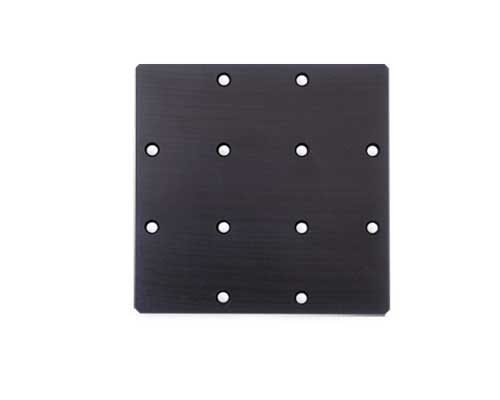
MSPP-2
Multipurpose adapter plate (4.6″ x 4.6″ x 0.375″)

MSPP-3 Adapter Plate

MSPP-4 Adapter Plate
Use to mount Rotary Table (A59 or B59 Series) to BiSlide Linear Stages

MSPP-5 Adapter Plate
Use to end mount BiSlide extrusion.

MSPP-6
Adapter plate to end mount BiSlide Linear Stage to an optical bench

XS001-20 Adapter Plate
Connects an XSlide™ Linear Stage to a BiSlide Linear Stage.

MB-1 Mounting Bolts
BiSlide® Bolt - 1/4-20 x 3/4" Socket Cap Screw (10 Pack)

MB-1-SS Mounting Bolts
BiSlide® Bolt - 1/4-20 x 3/4" Stainless Steel Socket Cap Screw

MB-2 Mounting Bolts
BiSlide® Bolt - 1/4-20 x 1/2" Buttonhead

MC-1 BiSlide® Cleat
Standard 1 hole cleat. Mounts the BiSlide to a frame / base / surface. Can be used to mount to other BiSlides in an XY, XZ or XYZ configuration.

MC-2 BiSlide® Cleat
Standard 2 hole cleat. Mounts the BiSlide to a frame / base / surface. Can be used to mount to other BiSlides in an XY, XZ or XYZ configuration.

MC-3 BiSlide® Cleat
2 hole cleat with 2″ center to center for use with optical benches with 1″ or 25 mm centers.

MC-4 BiSlide® Cleat
Sandwich cleats – used to connect two parallel bases.

MTN-1 T-Nuts
Use to create strong, secure attachments on BiSlide Assemblies.

BiSlide® Base Material
The extruded I-beam base is made from a hard alloy aluminum and includes T-slots on each side to easily connect BiSlides to each other or attach the BiSlide to a frame or base structure.

BiSlide® Foot
Acts as an adjustable foot for BiSlide bases and post assemblies. (LFS-1) (Shown with a MSPP-1 foot plate.)
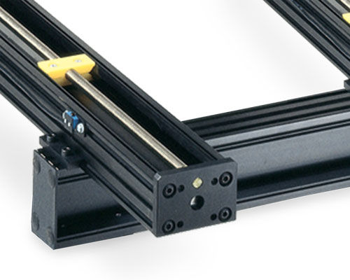
F2 Style BiSlide® Base
These bases have I-Beam top rails running parallel on two sides and are ideal for supporting parallel coupled BiSlide® Assemblies.
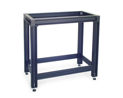
F4 Style BiSlide® Base
F4 Style bases have I-Beam top rails on all four sides for maximum support of heavy loads.

Support Rails
BiSlide® Support Rails are attached to the frame or a surface to provide added support to the system, particularly multi-axis configurations.

T-Slot Plate
T-Slot Plate creates a heavy-duty support structure for building BiSlide mounting and framing structures or configuring multiple coordinates.

GST-1 BiSlide® Gusset
A compact, standard vertical support gusset that increases stiffness and stability for vertically mounted BiSlide® systems in free-standing, side-mounted, or horizontal configurations.

GST-2 BiSlide® Gusset
A larger, heavy-duty vertical support gusset designed to provide increased rigidity and load support for taller or higher-moment BiSlide® assemblies in free-standing, side-mounted, or horizontal configurations.

GST-U BiSlide® Gusset
A fully configurable, inline-mounted vertical support gusset that delivers maximum stiffness for custom-length, high-load, and tall BiSlide® positioning systems.

Post Assemblies
Attach at right angles to the BiSlide® Assembly to provide a convenient method to connect rotary tables or other accessories at a right angle, a distance from the carriage surface. Supports an adapter plate either vertically or horizontally.

BiSlide® Way Covers
Way Covers protect the slider and dovetail base from dust, dirt and grit that could hamper the efficient operation of the slide, thereby extending the life of the slide.

BiSlide® Additional Carriages
Additional carriages (sliders) can be added to all models of BiSlide® Assemblies to increase the carrying capacity of the slide.
BiSlide® Limits
Limit switches mounted in the track on the side rib of the assembly to prevent over-travel.

BiSlide® Revolution Counter (-12, -13, -14, -15)
The mechanical counter provides a convenient lead screw revolution count. This aids in determining position and providing a reference number for the location of the carriage / slider.

BiSlide® Scale on Base
The BiSlide® Scale on Base option includes a precision engraved English or Metric scale on the assembly base.
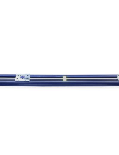
BiSlide® Two Independent Carriages
A single BiSlide® assembly containing two independently controlled sliders and lead screws.

Encoders

Manual BiSlide® Left-Right Screw Motion
When the knob is turned, two objects sharing a common axis of movement move toward or away from each other.

Motorized / Manual Operation

Right Angle Gearbox
Allows the control knob or wheel to be offset perpendicular to the BiSlide ways / centerline.
VRO™ Encoder Readout
The Velmex VRO™ Encoder Readout is a compact one or two axes digital readout for linear and rotary incremental encoders.
Velmex offers a multitude of options and accessories for all its products. Usually an option or an accessory will address your requirements. When it doesn’t, we can make custom modifications, including:
• Additional holes or slots. (A drawing is required.)
• Intermediate plates to mount your payload
• Special or in between lengths of the dovetail base
• Lead screw shaft extensions
• Choice of drive nut materials, including brass and Vespel
• Right and left-hand threads on the same lead screw, allowing a pair of sliders to move together or apart.
We can also offer customized configurations to address special environmental and vacuum applications.
Applications and Examples
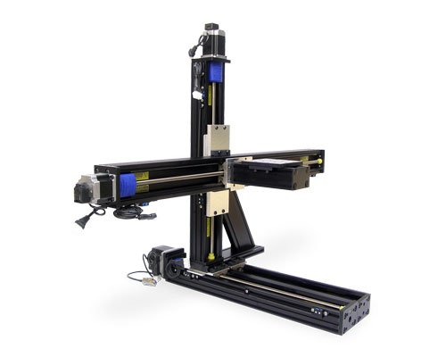
Note: the example displayed may be a custom configuration, designed to the customer’s specifications; and not offered as a standard product. Custom configurations could contain custom, externally-fabricated components.

Downloads
The majority of CAD drawings found in our Technical Library are Step (.stp) files. You will also see .dxf, .dwg, .sat and .pdf files. For .STP files, you may need to right click on the download button and save the “target” or “link”. If you require a different format or cannot located the drawing you require, please contact us.
| Title | Summary | File Type | Link | hf:file_type |
|---|---|---|---|---|
| BiSlide Catalog | Overview of BiSlide® Assembles – manual and motorized | |||
| BiSlide Dimensional Drawing | 2D Dimensional Drawings | |||
| BiSlide User Guide LEGACY models | LegacyUser’s Operating Manual for BiSlide Assemblies built before March 2019 with StabliNut I™ drive nut. | |||
| BiSlide Users Guide Current | Current User’s Operating Manual for BiSlide Assemblies built after March 2019 with StabiNut II™ drive nut | |||
| MT10-0050-xxx-31 4Cleats PK296.stp | Tandem, Lead screw, BiSlide, 5″ Travel, PK296 Stepper- 4 Cleats | stp | stp | |
| MT10-0100-xxx-31 6Cleats PK296.stp | Tandem, Lead screw, BiSlide, 10″ Travel, PK296 Stepper- 6 Cleats | stp | stp | |
| MT10-0150-xxx-31 8Cleats PK296.stp | Tandem, Lead screw, BiSlide, 15″ Travel, PK296 Stepper- 8 Cleats | stp | stp | |
| MT10-0200-xxx-31 10Cleats PK296.stp | Tandem, Lead screw, BiSlide, 20″ Travel, PK296 Stepper- 10 Cleats | stp | stp | |
| MT10-0300-xxx-31 12Cleats PK296.stp | Tandem, Lead screw, BiSlide, 30″ Travel, PK296 Stepper- 12 Cleats | stp | stp | |
| MT10-0400-xxx-31 14Cleats PK296.stp | Tandem, Lead screw, BiSlide, 40″ Travel, PK296 Stepper- 14 Cleats | stp | stp | |
| MT10-0500-xxx-31 16Cleats PK296.stp | Tandem, Lead screw, BiSlide, 50″ Travel, PK296 Stepper- 16 Cleats | stp | stp | |
| MT10-0600-xxx-31 18Cleats PK296.stp | Tandem, Lead screw, BiSlide, 60″ Travel, PK296 Stepper- 18 Cleats | stp | stp | |
| MT10-0800-xxx-31 20Cleats PK296.stp | Tandem, Lead screw, BiSlide, 80″ Travel, PK296 Stepper- 20 Cleats | stp | stp |
Knowledge Base

| Motion | Linear |
|---|---|
| Maximum Travel | 80" (203.2 cm) |
| Minimum Travel | 5" (12.7 cm) |

